Users will be able to setup an experiment using jFed. After the user sends the login information, the AM will authenticate the user, tell him/her which resources will be available to them through RSpecs, and interact with the CBTM on behalf of the user in order to instantiate the available resources.The AM
uses the GENI v3 API which is written as a wrapper of the reference AM.
The USRP (Universal Software Radio Peripheral) is a software-defined radio, which is able to run arbitrary code using an FPGA as well as on the CPU of the server. It can be used to run any wireless standard (including existing standards or even a protocol that has been created by the experimenter), as long as the operating frequency and other parameters of the communication are within the accepted range of the USRP card. This section describes how to book an USRP and how to run a very simple experiment that checks for the spectrum usage on a certain frequency.
The USRP nodes are allocated as virtual machines containing USRP boards attached via USB. Each MiniPC on the testbed can support one USRP node at a time. The RSPEC for allocating an USRP node must contain the following tags:
The bold part inside of the “node” tag indicates that this node is being allocated in the UFMG FUTEBOL testbed. It is automatically filled with this information when the UFMG testbed is selected on the dropdown menu on jFed. The name component on the “sliver_type” tag indicates that this node is composed of a virtual machine containing an USRP board attached to it via USB. Inside the “sliver_type” tag is the “disk_image” tag. This tag selects the type of virtual machine that will be allocated. The “name” component inside this tag indicates which type of virtual machine is being allocated, and also reinforces that this
machine is being allocated inside of the UFMG Testbed. The string on the “name” component must follow the structure pre
sented above. The IMG_TYPE can be one of the following:
In this experiment we are going to run a spectrum analyser, which will use the USRP to show how is the usage of the medium on a certain frequency. To that end, we will instantiate a USRP resource on the UFMG FUTEBOL testbed. The following RSPEC can be used to instantiate a single VM with a USRP:
After the VM is instantiated, you can execute commands to perform experiments in the USRP. The first basic command is to check if the equipment is detected. To do this, run the command uhd_find_devices. This command output will indicate the model, serial number and name of the USRP that is connected to the virtual resource that you allocated.
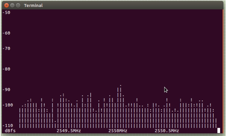
On the ‘rx_node’, run the following code. This code will run a frequency analyzer at 2.55GHz, sampling the medium at a rate of 2MHz. This frequency analyzer runs on the command line (because it may be too slow to open a graphic user interface from the testbed).
The Raspberries PI are single board computers, used in this testbed to simulate Access Points, Wireless Stations or plain computers. This sectiondescribes how to allocate a Raspberry PI and how to run simple experiments to check the operability of the devices.
The example below shows an RSPEC for allocating a Raspberry Pi as a Wireless Station
(note that the mode of the WiFi card is defined by the mode parameter of the sliver, being
either ap or sta):
It is possible to use the MiniPCs to perform experiments using WiFi. The Mini PCs use a Dell Dual band Wireless AC 8620 chipset, which has 2x2 MIMO and supports IEEE 802.11 a, b, g, n and ac standards. The Raspberry Pis can also be used for WiFi experiments (please check the appropriate section), however the Mini PCs have a much wider configuration range.
Besides using the command line tools to configure the WiFi, it is also possible to use a SDN interface called Ethanol to control them. Ethanol is able to control a number of parameters of the wireless interface from a SDN controller. Those can be used in SDN based experiments, or as a tool to control the WiFi links in your experiment. For example, you can force a node disconnect using Ethanol, to emulate a node failure. The full documentation of the Ethanol API can be found in github: https://github.com/h3dema/ethanol_controller/tree/master/ethanol/documentation
The WiFi nodes can be allocated as a machine with wireless network card.Note that the WiFi node is selected by using the sliver type raw-wifi. The example below presents an RSPEC for WiFi node, using Ubuntu 16.04:
After allocating the machines with wifi, follow the steps below:
1. Define the IP addresses so that the hosts are on the same network.
2.
Using hostAPd it is possible to create an access point using a configuration file, for example named hostapd.conf, such as the one below:
3. Then run hostapd on the AP machine with this file.
4. Next, establish a connection between the hosts and the access point.
In the client, please run:
For more examples of experiments with WiFi, see our User Guide.
The Advanticsys MTM-CM5000-MSP is a wireless sensor node with limited processing and network resources. It is recommended for experiments on wireless sensor networks or related to Internet of Things with very resource constrained devices. The nodes transmit wirelessly using the standard IEEE 802.15.4. In order to program the nodes, the programmer must create a binary integrating his/her own code with one operating system, which is either TinyOS or Contiki. The Advanticsys is a node that is compatible to any software developed for the TelosB platform. It has temperature, relative humidity and light sensors. They are connected via an USB interface. More information at https://www.advanticsys.com/shop/mtmcm5000msp-p-14.html.
Sensor nodes must be allocated together with a virtual machine that contains the system responsible for managing the sensor nodes. To do this, the sliver_type attribute is set to telosb-vm and disk_image as telosb. For each instance of the sensor nodes, just configure
the sliver_type as raw-telosb. Note that it is not necessary to use the disk_image attribute for the sensor nodes.
In this experiment we will demonstrate the operation of the applications Oscilloscope and BaseStation which are both examples of the TinyOS Operating System. The first is a simple demo of data collection responsible for periodically the voltage sensor and transmitting on the radio a message with 10 consecutive readings. The second application receives messages from the radio and forwards them to the PC through the USB port. Below we demonstrate the experience, being allocated node 60 for oscilloscope,node 66 for BaseStation and a virtual machine.
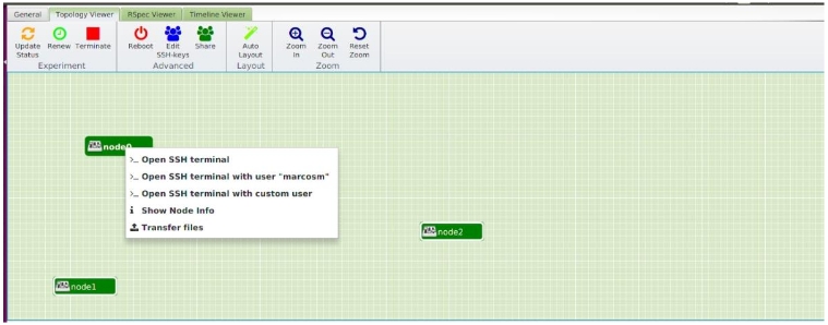
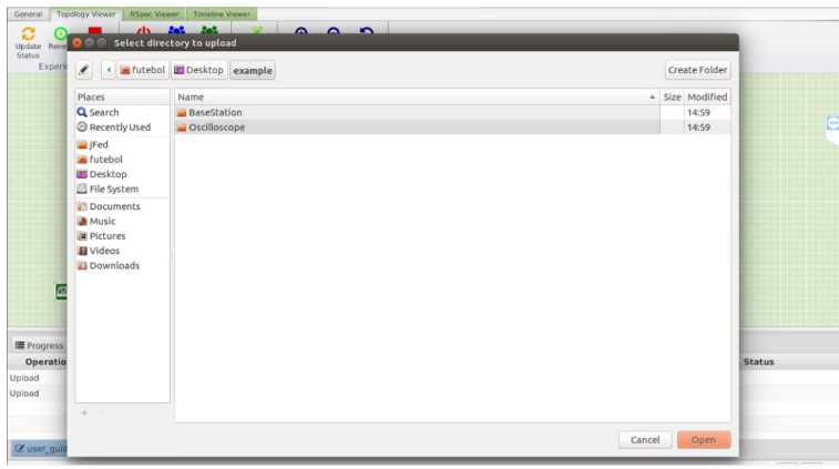
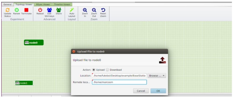
After the nodes are allocated, you must first send your to the allocated virtual machine, compile it through the TinyOS operating system, and compress the resulting files with a .zip extension. We then send the Oscilloscope and BaseStation folders through the Transfer Files option in Jfed.
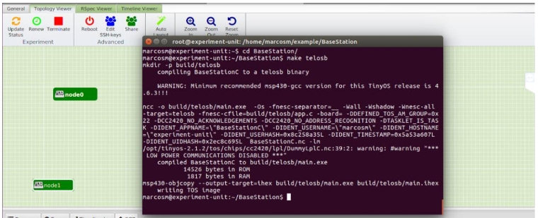
Now, access the virtual machine allocated through the terminal (node 0 in Jfed), navigate to the folder of your application and execute the command make telosb to generate the executable that will be installed in advanticsys nodes.
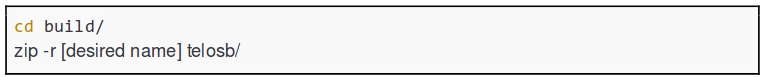
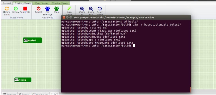
The build folder will be automatically created, containing the executable and other necessary files. Navigate to it and run the command below to compress the files.
As an alternative, you can compile 2 and compress the data on your own computer and transfer the .zip file through the Jfed Transfer File function for this, see how to install the TinyOS Operating System on your computer.
To perform the installation of the applications on the sensor nodes, simply run the command below on the terminal of the virtual machine (node 0 in the example allocation).
On your terminal you will receive a success message or some error message. In the event of an error, repeat the installation procedure. On success, the sensor nodes will be working according to their application and the collected data will be saved in text files during the
useful period of the experiment.
At any time during your experiment time you can request the data collected through the receiving node, by means of the command below, which should be executed in the terminal of the virtual machine.
Notice that the recv command calls the procedure for receiving the files, and the -node parameter specifies which node you want to receive the data from. The procedure is responsible for sending to the allocated virtual machine a compressed file that contains the
data of the experiment. You can view this file in the VM's personal folder or download it through Jfed.
Experiments with Virtual Machine
Experiments with USRP
RSpec Description
The “disk_image” tag is optional. When the “sliver_type” selected is “usrp-vm”, the default image selected for the machine is “gnuradio”.
Example Experiment
Download our example
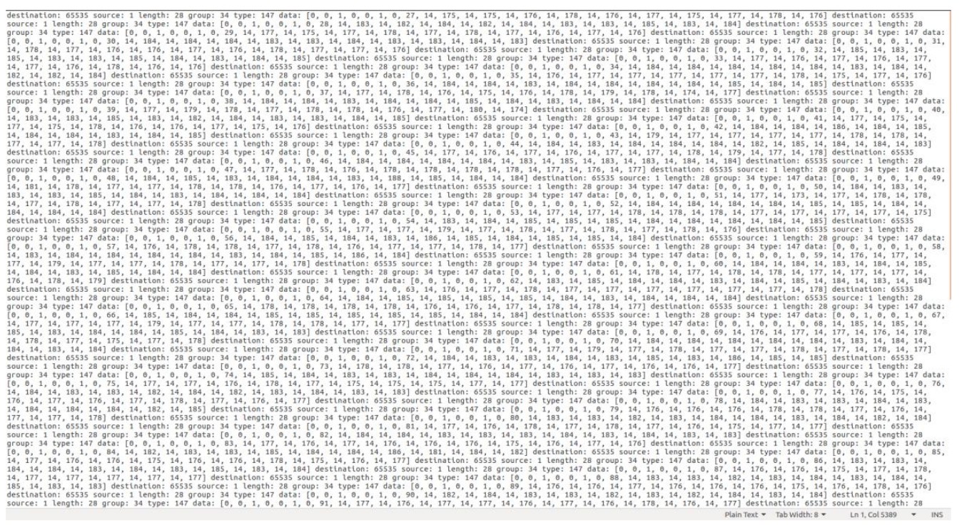
You should be able to see the ascii representation of the transmitted waveform spectrum, as illustrated below:
Experiments with Raspberry Pi
Raspberry Pi RSpec Description
The Raspberry Pi nodes can be allocated as Access Points, Wireless Stations or Without Both Configurations. Note that the raspberry Pi is selected by using the sliver type raw raspberry. The example below presents an RSPEC for a Raspberry Pi mote operating as an Access Point:
The wifi-settings tag holds the configuration items for the Wireless interface. The options in this tag are:
The example below shows an RSPEC for allocating the Raspberry Pi without configuring its WiFi interface:
Examples of a Raspberry Pi Experiments
Plain Raspberry Pi
The example below show a complete RSpec to allocate a plain Raspberry Pi.
After the allocation of the Raspberry Pi node is done, the device can be tested using the simple code below:
The example code can be downloaded, compiled and executed as follows:
TERMINAL OUTPUT
For more examples of experiments with raspberry pi, see our User Guide.
Experiments with WI-FI
RSpec Description
The example below shows an RSPEC for allocating the WiFi node using Ethanol:
Example Experiments - WiFi node without Ethanol
Below shows an RSPEC for allocating the WiFi node for this experiment:
Download our example
5. You can test the performance with the Iperf tool, which comes pre-installed in the image. In the server, run:
Experiments with Advanticsys Sensor Nodes
At the moment, the FUTEBOL UFMG testbed supports programming the Advanticsys using the TinyOS operating system. In the future we lan to support Contiki as well.
RSpec Description
You can specify which node to allocate according to the ID shown in Figure 2 by configuring the component_id attribute of each node tag with the specific number of the sensor node.
The example below shows an RSPEC with one virtual machine (named node 0) and two sensor nodes (60 and 66, named node 1 and node 2).
Download our example
Example Experiment
Note that the -node and -file parameters specify which node to install the application and the file name, respectively.
To know more about the fields on this experiment,please visit the official page of tinyos. For our example, see the output file.
futebol.dcc.ufmg.br